
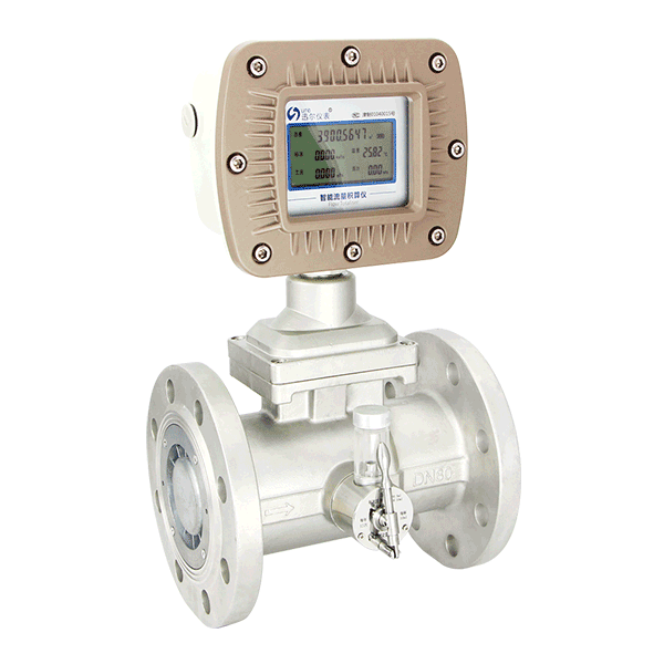
DESCRIPTION:The Gas turbine flow meter in the secies LWQ are specially designed for use in natural gas. compressed, air and other fluid measurement. And the volume and mass flow rate are available.
The operation of the International Gas Turbine Meter is based on the measurement of the velocity of gas The flowing gas is accelerated and conditioned by the meters straightening section. The straightening vanes prepare the gas flow profile by removing undesired swirl, turbulence and asymmetry before the gas flows lo (he turbine wheel. The dynamic forces of the flowing fluid cause the rotor to rotate.
The turbine wheel is mounted on the main shaft, with special high precision, low friction ball bearings. The turbine wheel has helical blades that have a known angle relative to the gas flow. The conditioned and accelerated gas drives the turbine wheel with an angular velocity that is proportional with the gas velocity.
The Gas turbine flow meter in the secies LWQ are specially designed for use in natural gas. compressed, air and other fluid measurement. And the volume and mass flow rate are available.
-DN25-DN400
-Temp.& Press, compensation
-Communication: RS485
-Connection: Thread / Flange
-Ten units are optional
|
Output Pulse |
Pulse |
|
4~20mA |
|
|
Accuracy |
±1.0%ofRate |
|
Operating Temperature |
-20...+60°C |
|
Fluid Temperature |
-20...+80°C |
|
Body Material Cast Aluminium |
SS 304 (D4:DN50-DN200) |
|
Rotor Material |
Aluminum alloy |
|
Bearing Material |
SS304 |
|
Model |
Suffix Code |
Description |
||||||||
|
Diameter |
XXX |
|
|
|
|
|
|
|
|
Stand for diameter 020: DN20: DN050: DN50 100: DN100: 400: DN400 |
|
Converter Type |
N |
|
|
|
|
|
|
|
24V DC; Pulse output; No display |
|
|
A |
|
|
|
|
|
|
|
24V DC; 4-20 mA output; No display; Ex |
||
|
E1 |
|
|
|
|
|
|
|
Battery power supply; No output; Ex; Digital display |
||
|
E2 |
|
|
|
|
|
|
|
24V DC; 2-wire 4-20mA output; Ex; Digital display |
||
|
E3 |
|
|
|
|
|
|
|
24V DC; Pulse output; Local display; Ex; display |
||
|
E4 |
|
|
|
|
|
|
|
24V DC; 0-20mA output; Local display; EX;Digital display |
||
|
E5 |
|
|
|
|
|
|
|
24V DC; 3-wire 4-20mA / Pulse output; EX; Digital display |
||
|
FE |
|
|
|
|
|
|
|
Fluidwell E series converter |
||
|
FF |
|
|
|
|
|
|
|
Fluidwell F series converter |
||
|
D1 |
|
|
|
|
|
|
|
24V DC; 2-wire 4-20mA output; Digital display; Temperature & Pressure Compensation |
||
|
D2 |
|
|
|
|
|
|
|
24V DC; 3-wire 4-20mA output; Digital display; Temperature & Pressure Compensation |
||
|
D4 |
|
|
|
|
|
|
|
24V DC; 4-20mA output; Modbus RS485; Digital display; Temperature & Pressure Compensation |
||
|
Notice: |
|
|
|
|
|
|
|
1)Modbus RS485 is optional for E2,E3,E4,E5,D1,D2,D4 |
||
|
2)Battery Power(24V DC+Battery) is optional for E2,E3,E4,E5,D1,D2,D4 |
||||||||||
|
3)D4 is only cast steel available |
||||||||||
|
Accuracy |
10 |
|
|
|
|
|
|
±1.0% of Rate |
||
|
15 |
|
|
|
|
|
|
±1.5% of Rate |
|||
|
Flow Range |
S |
|
|
|
|
|
Standard Range |
|||
|
E |
|
|
|
|
|
Extended Range |
||||
|
Body Material |
S4 |
|
|
|
|
SS304 |
||||
|
S6 |
|
|
|
|
SS316 |
|||||
|
CA |
|
|
|
|
Cast Aluminum |
|||||
|
CS |
|
|
|
|
Cast Steel (Only for D4 Type) |
|||||
|
Rotor Material |
AB |
|
|
|
ABS Plastic |
|||||
|
AA |
|
|
|
Aluminum Alloy |
||||||
|
Explosion Proof |
BT |
|
|
Exd II BT6 |
||||||
|
CT |
|
|
Exd II CT4 |
|||||||
|
NA |
|
|
No explosion proof |
|||||||
|
Connection |
THM |
|
Male thread; Available from DN4 ... DN50 |
|||||||
|
THF |
|
Female thread; Available from DN4 ... DN50 |
||||||||
|
DXX |
|
D16: DIN PN16 flange; D25: DIN PN25… |
||||||||
|
AXX |
|
A15: ANSI 150# flange; A30: ANSI 300#... |
||||||||
|
JXX |
|
J10: JIS 10K flange; J20: JIS 20K… |
||||||||